A micro hydro power plant is a small-scale hydroelectric system (typically up to 100 kW) that generates electricity using the natural flow of water from a river or stream. It is widely used in remote or rural areas due to its simplicity, low cost, and renewable nature.
With the help of a neat diagram, explain the layout & working of a micro hydro power plant.
Components:
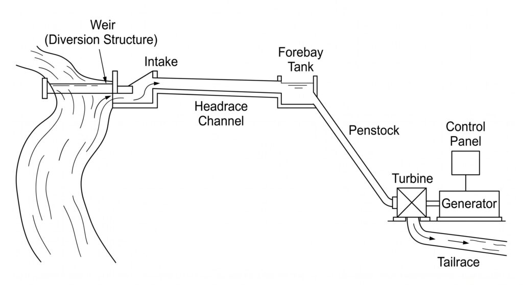
A micro hydropower plant generates electricity from the natural flow of water. Its components work in sequence, each passing water to the next.
- Weir — A small dam built across the stream to divert water away from the main river and into the plant system.
- Intake — The entry point of the diverted water. A trash rack (metal screen) is fitted here to block leaves, stones, and debris.
- Headrace Channel — A channel or pipe that carries water from the intake to the forebay tank. It is designed to move water with minimum loss of pressure or speed.
- Forebay Tank — A small tank where water is stored for a short time. Mud and sand settle down here, so clean water moves forward.
- Penstock — A sealed, high-pressure pipe that carries water steeply downhill from the forebay to the turbine. The drop in height builds up the pressure and speed of water.
- Turbine — The fast-moving water strikes the turbine blades, causing them to spin. This converts the energy of water into mechanical (rotational) energy.
- Generator — Directly connected to the turbine shaft. As the shaft spins, the generator converts mechanical energy into electrical energy.
- Control Panel — Monitors, controls, and protects the electrical system from faults and overloads.
- Tailrace — A channel that carries the used water away from the turbine and returns it back to the river.
Working of Micro Hydro Power Plant
A micro hydro power plant works by converting the potential and kinetic energy of water into electrical energy.
Water from a river is diverted by a weir and enters through an intake, where a trash rack removes debris.
It then flows through the headrace channel to the forebay tank, where sediments settle and flow is regulated. From there, water passes through the penstock under high pressure and strikes the turbine blades, causing rotation.
The turbine drives the generator to produce electricity, which is supplied to the load through a control panel. Finally, the used water is discharged back to the river through the tailrace.
Classify different types of water-turbines used in Micro Hydro power plants.
Water turbines are classified mainly on two bases—the type of energy at the inlet and the head of water available.
1. Based on Type of Energy at Inlet
(a) Impulse Turbines—Suitable for high head and low flow conditions. (Pelton Wheel)
(b) Reaction Turbines—Suitable for low to medium-head and high-flow conditions. (Francis Turbine, Kaplan Turbine)
2. Based on Head of Water
(a) High Head Turbines– Used when head is more than 100 meters. (Pelton Turbine)
(b) Medium Head Turbines-Used when head is between 30 and 100 meters. (Francis Turbine)
(c) Low Head Turbines-Used when head is less than 30 meters. (Kaplan Turbine)
Different Types of Water Turbines Used in Micro Hydro Power Plants with Explanation
1. Based on Type of Energy at Inlet
(a) Impulse Turbines
These turbines work using only the kinetic energy of water. Water is first converted into a high-speed jet through a nozzle. This jet then strikes the blades of the turbine and makes it spin. There is no pressure acting on the blades during rotation. They work best where the head is high and the flow of water is low.
Common examples of impulse turbines are the Pelton Wheel, Turgo Turbine, and Cross-flow (Banki) Turbine.
(b) Reaction Turbines
These turbines work using both pressure energy and kinetic energy of water. Water flows around and over the blades continuously. The pressure difference across the blades causes the turbine to rotate. The turbine runs fully submerged in water. They work best where the head is low to medium and the flow of water is high.
Common examples of reaction turbines are the Francis Turbine, Kaplan Turbine, and Propeller Turbine.
2. Based on Head of Water
(a) High Head Turbines
These are used when the head of water is more than 100 metres. At this height, water has very high speed and pressure. The Pelton Turbine and Turgo Turbine are the most suitable choices for high head conditions.
(b) Medium Head Turbines
These are used when the head of water is between 30 and 100 metres. Water has moderate speed and pressure at this range. The Francis Turbine works best under medium head conditions.
(c) Low Head TurbinesThese are used when the head of water is less than 30 metres. Here the flow of water is high but the pressure is low. The Kaplan Turbine, Propeller Turbine, and Cross-flow Turbine are suitable for low head conditions.