The Francis turbine is a reaction-type turbine where water flows radially inward and then axially outward, making it suitable for medium head and moderate flow conditions with high efficiency. The Pelton turbine is an impulse turbine in which high-speed water jets strike the runner buckets; it is mainly used for high head and low flow conditions, operating in atmospheric pressure. The Kaplan turbine is also a reaction turbine where water flows parallel to the axis, and due to its adjustable blades, it performs efficiently under low head and high flow conditions and is commonly used in river-based hydro plants.
Francis Turbine
Construction of Francis Turbine
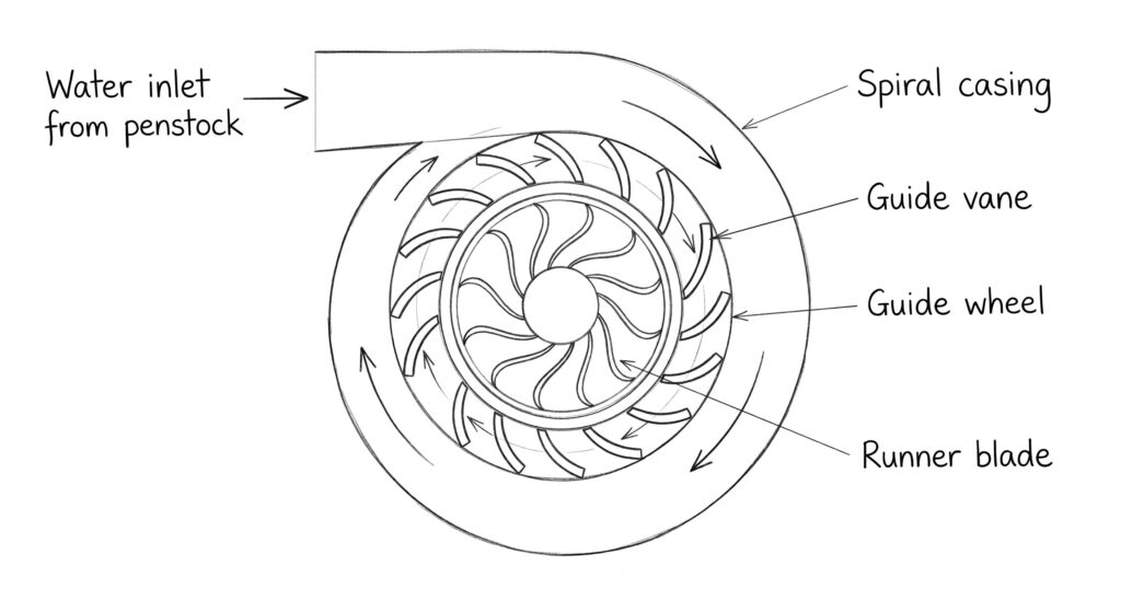
A Francis turbine is a reaction turbine in which water flows radially inward and exits axially. The main components are:
- Spiral Casing (Volute):
A spiral-shaped casing surrounding the runner. It distributes water uniformly around the turbine. - Guide Vanes (Stay & Guide Blades):
Adjustable vanes that control the flow rate and direct water at the proper angle onto the runner. - Runner:
The rotating part consisting of curved blades. It converts hydraulic energy into mechanical energy. - Shaft:
Connects the runner to the generator. - Draft Tube:
A gradually expanding tube fitted at the outlet. It reduces exit velocity and recovers pressure energy. - Casing and Bearings:
Support and enclose the turbine system.
Working of Francis Turbine
The working of a Francis turbine is based on the reaction principle, where both the pressure and kinetic energy of water are utilized.
Water from the reservoir enters the spiral casing under pressure and is distributed uniformly. It then passes through the guide vanes, which regulate and direct the flow towards the runner at the desired angle.
The water enters the runner radially and strikes the curved blades, causing a change in pressure and velocity. Due to this change, the runner starts rotating.
The rotating runner drives the shaft, which is connected to a generator, thereby producing electrical energy. After passing through the runner, water exits in the axial direction and enters the draft tube.
The draft tube reduces the velocity of water and finally discharges it to the tailrace with improved efficiency.
Pelton Turbine
Construction of Pelton Turbine
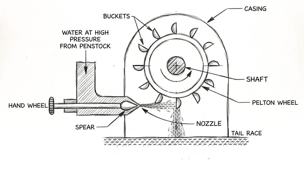
A Pelton turbine is an impulse turbine used for high head.
- It consists of a runner mounted on a shaft, fitted with double-cup (bucket) shaped blades having a splitter.
- Water is supplied through a penstock to a nozzle, which converts pressure energy into a high-speed jet.
- A spear (needle valve) is used to regulate the flow rate of water.
- The turbine is enclosed in a casing to prevent splashing and guide water to the outlet.
Working of Pelton Turbine
The water from the penstock is converted into a high-velocity jet by the nozzle and directed tangentially onto the buckets of the runner.
The jet strikes the splitter of each bucket and gets divided into two streams, which are deflected in opposite directions. This change in momentum of water produces an impulse force that rotates the runner.
Since the pressure of water remains atmospheric throughout the process, the energy transfer occurs purely due to kinetic energy. After imparting energy, the water falls into the tailrace with reduced velocity.
Kaplan Turbine
Construction of Kaplan Turbine
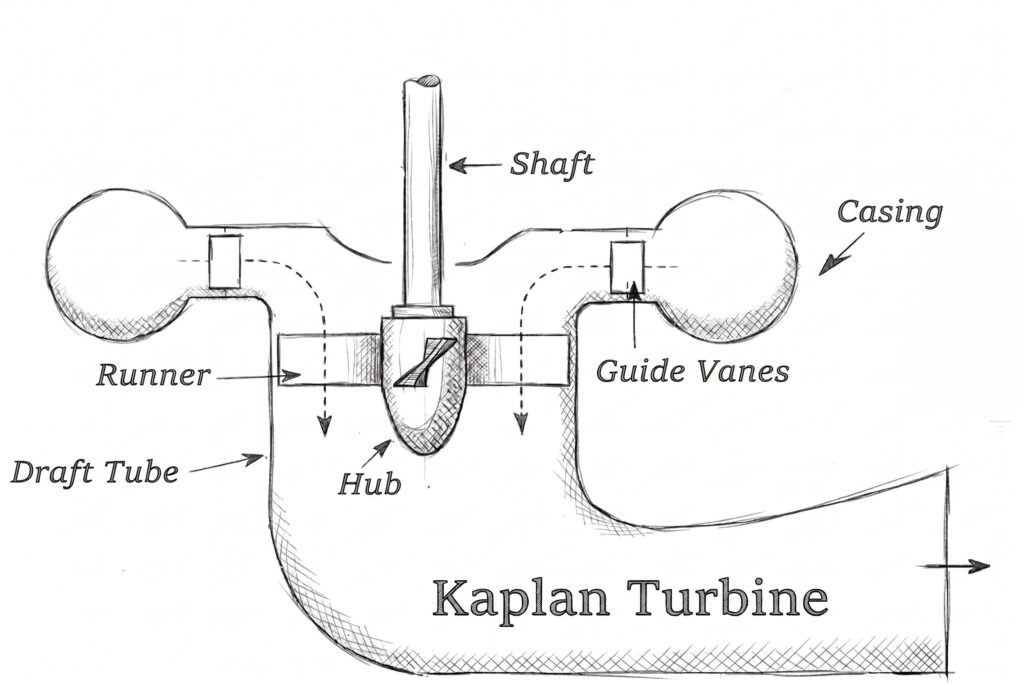
A Kaplan turbine is a reaction turbine used for low head and high discharge.
- It has a propeller-type runner with adjustable blades mounted on a central hub.
- Water enters through a spiral casing and passes through guide vanes, which control flow direction.
- A draft tube is provided at the outlet to recover kinetic energy.
- The turbine shaft may be arranged vertically or horizontally.
Working of Kaplan Turbine
Water enters the turbine through the spiral casing and flows through the guide vanes, which regulate the quantity and direction of flow.
It then passes axially through the runner, causing the blades to rotate due to both pressure and velocity changes. The adjustable blades automatically change their angle to maintain high efficiency under varying loads.
As the water moves through the runner, its pressure decreases, and energy is transferred to the turbine shaft. Finally, the water exits through the draft tube, where some of the kinetic energy is converted into pressure energy.