A capacitor is a passive component and a small but very important part of an electronic circuit. Its main job is to store electrical charge for a short time and then release it when needed. You can think of a capacitor like a tiny storage tank for electricity.
Capacitors are used in almost all electrical and electronic devices. They help smooth power supply, reduce noise, store energy, and control the flow of current. Because of these uses, capacitors are found in mobiles, TVs, chargers, computers, and many other devices.
What is a Capacitor?
A capacitor is a two-terminal electronic component that stores electrical charge for a short time. It has two metal plates placed close to each other, separated by an insulating material called a dielectric.
or,
A capacitor is an electrical component that opposes sudden changes in voltage across it by storing and releasing electrical charge.
What is Capacitance?
Capacitance is the ability of a capacitor to store electrical charge. It tells us how much charge a capacitor can store for a given voltage.
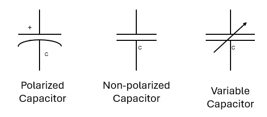
Symbol
Unit
The SI unit of the capacitance is Farad (F). The unit farad is named after Michael Faraday, a famous scientist who discovered the law of electromagnetic induction.
The CGS unit of capacitance is often referred to as the statfarad (statF).
One farad is a very large unit of capacitance. Because of this, most practical capacitors have much smaller values. Therefore, capacitors are usually rated in:
- microfarad (µF) = 1 × 10⁻⁶ F
- nanofarad (nF) = 1 × 10⁻⁹ F
- picofarad (pF) = 1 × 10⁻¹² F
Construction of Capacitor
A capacitor is constructed using two conducting plates placed very close to each other. These plates are usually made of metal such as aluminium or copper. The plates do not touch each other; they are separated by an insulating material called a dielectric.
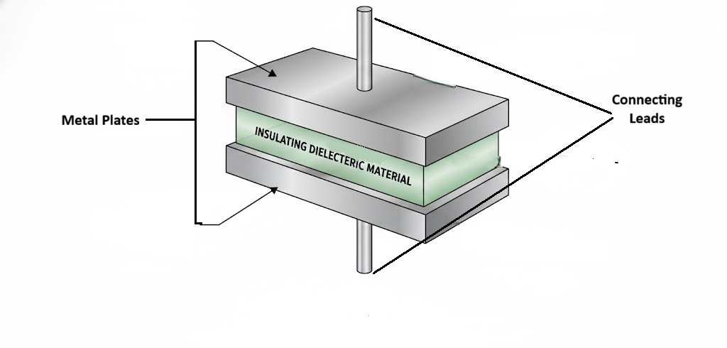
The dielectric can be made of air, paper, mica, ceramic, plastic, or oxide film, depending on the type of capacitor. This dielectric helps increase the capacitance and prevents current from flowing directly between the plates.
Each plate of the capacitor is connected to a terminal. When a voltage is applied across these terminals, electrical charge gets stored on the plates. One plate becomes positively charged and the other becomes negatively charged.
The basic construction of a capacitor depends on three main factors:
- Area of the plates
- Distance between the plates
- Type of dielectric material used
By changing these factors, different types and values of capacitors are made.
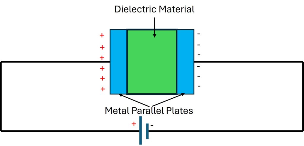
Working Principle of Capacitor
The working principle of a capacitor is based on the storage of electrical charge in an electric field. When a voltage source is connected across the terminals of a capacitor, electrons start moving and charge begins to build up on the plates.
One plate of the capacitor collects negative charge, while the other plate loses electrons and becomes positively charged. The dielectric material between the plates does not allow current to flow directly, but it allows an electric field to form between the plates.
As charging continues, the voltage across the capacitor increases. When the capacitor voltage becomes equal to the applied voltage, charging stops. At this point, the capacitor is fully charged and acts like an open circuit for DC.
When the voltage source is removed and a load is connected, the capacitor releases the stored charge. This process is called discharging. During discharging, the capacitor supplies current to the circuit until the stored energy is used up.
This charging and discharging action is the basic working principle of a capacitor
Capacitance Formula
Capacitance is defined as the ratio of electric charge stored on a capacitor to the voltage applied across it.
Formula:
Where:
- C = Capacitance (in Farad, F)
- Q = Charge stored (in Coulomb, C)
- V = Voltage applied (in Volt, V)
For a parallel plate capacitor, the capacitance is also given by:
Where:
- ε₀ = Permittivity of free space (ε0=8.854×10⁻¹² F/m )
- εᵣ = Relative permittivity of dielectric (Absolute Permittivity (ε)= ε₀εᵣ )
- A = Area of plates
- d = Distance between plates
This formula shows that capacitance increases with larger plate area and better dielectric material and decreases when the distance between plates increases.
Types of Capacitors
According to Structure
Based on their construction, capacitors are classified into the following types:
- Fixed Capacitors
These capacitors have a fixed capacitance value that cannot be changed. - Variable Capacitors
In these capacitors, the capacitance value can be varied manually. They are mainly used in tuning circuits. - Trimmer Capacitors
Trimmer capacitors are small variable capacitors used for fine adjustment during circuit calibration.
According to Polarization
Based on polarity, capacitors are classified into two types:
- Polarized Capacitors
Polarized capacitors have positive and negative terminals and must be connected with correct polarity. These capacitors are commonly called electrolytic capacitors. They are used where high capacitance values are required. - Unpolarized Capacitors
Unpolarized capacitors do not have positive or negative terminals. They can be connected in any direction and do not get damaged by reverse voltage. These capacitors are suitable for AC circuits and are also used in DC circuits. They have high operating frequency and low leakage current.
Common Types of Capacitors
Below are the common types of capacitors used in electronic circuits:
1. Ceramic Capacitors
These capacitors use ceramic material as the dielectric. They are small in size and used in high-frequency and noise-filtering applications.
2. Film Capacitors
Film capacitors use plastic film as the dielectric. They offer good stability and are used in audio and signal circuits.
3. Mica Capacitor
Mica capacitors use mica as the dielectric. They are very stable and accurate and are used in high-frequency and radio circuits.
4. Electrolytic Capacitors
Electrolytic capacitors provide very high capacitance values. They are polarized and commonly used in power supply circuits.
5. Paper Capacitors
Paper capacitors use paper as the dielectric. They are mostly replaced by modern film capacitors but may still be found in older circuits.
6. Tantalum Capacitor
Tantalum capacitors are similar to electrolytic capacitors but are smaller in size and more stable. They are also polarized and used in compact electronic devices.
Series Combination of Capacitor
When two or more capacitors are connected in series, they form a series combination. In this type of connection, the capacitors are connected end-to-end, and the same charge flows through each capacitor.
In a series combination:
- The charge (Q) on each capacitor is the same
- The total voltage is equal to the sum of voltages across each capacitor
- The equivalent capacitance is less than the smallest capacitor in the series
Formula for Series Combination
Where:
- Cₛ = Equivalent capacitance
- C₁, C₂, C₃ = Individual capacitances
For two capacitors:
- Series combination is used when lower capacitance is required
- It is also used to increase voltage rating
- Widely used in high-voltage applications
Parallel Combination of Capacitor
When two or more capacitors are connected in parallel, they form a parallel combination. In this type of connection, all capacitors are connected across the same voltage source.
In a parallel combination:
- The voltage (V) across each capacitor is the same
- The total charge is equal to the sum of charges on each capacitor
- The equivalent capacitance is greater than the largest capacitor in the combination
Formula for Parallel Combination
Where:
- Cₚ = Equivalent capacitance
- C₁, C₂, C₃ = Individual capacitances
- Parallel combination is used when higher capacitance is required
- It increases the energy storage capacity
- Commonly used in power supply filtering circuits
Energy Stored in a Capacitor
A capacitor stores electrical energy when it is charged. This energy is stored in the electric field created between the two plates of the capacitor.
Formula for Energy Stored
The energy stored in a capacitor is given by:
Where:
- E = Energy stored (in joules, J)
- C = Capacitance (in farads, F)
- V = Voltage across the capacitor (in volts, V)
Proof of Energy Stored in a Capacitor
We know that capacitance is defined as:
So,
Work done in charging a capacitor:
When a small charge dQ is added to a capacitor, the potential difference across it at that moment is:
The small amount of work done dW in moving charge dQ against this potential is:
Substituting the value of :
Total work done:
To find the total work done in charging the capacitor from 0 to Q, integrate:Substitute
This proves that the energy stored in a capacitor is equal to ½ CV².
Capacitor in DC Circuit
When a capacitor is connected to a DC circuit, it first charges. At the moment of connection, it behaves like a short circuit and allows current to flow.
As it charges, the current gradually decreases. When the capacitor becomes fully charged, it blocks DC and behaves like an open circuit.
If the source is removed, the capacitor can discharge and supply current for a short time.
Capacitor in AC Circuit
In an AC circuit, a capacitor continuously charges and discharges because the voltage keeps changing direction. So, unlike DC, it does not become fully charged and blocked.
A capacitor allows AC current to pass, but it offers opposition called capacitive reactance. Higher frequency AC passes more easily, while lower frequency faces more opposition.
In a capacitor, current leads voltage in an AC circuit.
Applications of Capacitor
- Power supply filtering — smooths DC output by reducing ripple
- Energy storage — stores electrical energy for short time use
- Coupling — passes AC signals and blocks DC between stages
- Decoupling/Bypass — removes noise from circuits
- Motor starting — provides phase shift in single-phase motors
- Timing circuits — used in RC timers and oscillators
- Tuning circuits — used in radios and frequency selection
- Power factor correction — improves power factor in AC systems