Explain how Doubly-Fed Induction Generators (DFIG) are implemented in WECS to feed electric power into the grid in a variable wind speed environment.
In a DFIG system, the generator is a wound-rotor induction generator. It is “doubly-fed” because power is exchanged with the grid through both stator and rotor.
Stator and Rotor Connection
Stator Connection:
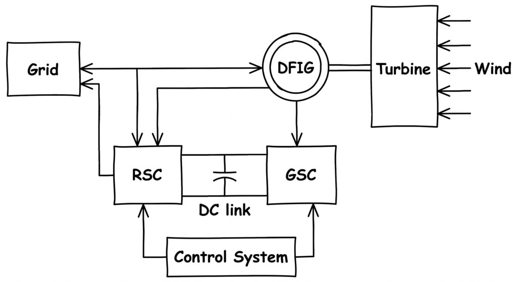
The stator is directly connected to the three-phase grid and supplies power at constant frequency.
Rotor Connection:
The rotor is connected to the grid through a back-to-back PWM bi-directional converter using slip rings. This allows control of rotor voltage and bidirectional power flow.
Converters
The converter has two parts:
(a) Rotor-Side Converter (RSC):
Controls active and reactive power by regulating rotor currents.
(b) Grid-Side Converter (GSC):
Maintains DC-link voltage and controls power factor, ensuring good power quality.
Variable-Speed Operation
By controlling rotor voltage, the DFIG operates at variable speeds for better energy capture.
(a) Sub-synchronous:
Rotor speed < synchronous speed; power flows from grid to rotor.
(b) Super-synchronous:
Rotor speed > synchronous speed; excess power flows from rotor to grid.
Frequency Control
Wind speed varies, so rotor speed (nr) changes, but grid frequency (fs) must remain constant.
fs=120P⋅nr±fr
By controlling rotor current frequency (fr), constant output frequency is maintained.
Fractional Power Conversion
Only a part of total power (slip power) passes through the converter, while the rest is directly supplied to the grid. This reduces converter size, cost, and losses.
Detailed DFIG Operation in WECS for Variable Wind Speed
Doubly-Fed Induction Generators (DFIGs) are among the most common electrical generators used in variable-speed Wind Energy Conversion Systems (WECS). They are implemented to feed electric power into the grid through the following key mechanisms and components:
1. Rotor Access and Bi-directional Converters Unlike standard squirrel-cage induction generators, DFIGs provide direct access to the rotor windings, making it possible to impress a rotor voltage. This means the generator can be magnetized from either the stator circuit or the rotor circuit. This is managed by a slip power recovery scheme that utilizes a bi-directional power converter, typically a back-to-back two-level converter.
2. Variable-Speed Operation By actively controlling the rotor voltage, the DFIG can operate as a generator at both sub-synchronous and super-synchronous speeds. The acceptable speed range is dictated solely by the converter ratings. This variable-speed capability enhances overall energy capture because rated torque is maintained at super-synchronous speeds, avoiding the torque reduction associated with field weakening in cage-rotor generators.
3. Independent Inverter Control The back-to-back converter consists of a grid-side inverter and a rotor-side inverter that are controlled entirely independently.
- Rotor-Side Control: This control structure takes the desired active and reactive power and compares them with actual measured values and rotor currents. The resulting errors are fed into PI-controllers that output d- and q-axis rotor voltage references. These references are then used to calculate the gating signals that control the rotor inverter. Detecting the required slip angle for this process is done using either an optical encoder or position-sensorless schemes.
- Grid-Side Control: The grid-side inverter can be controlled to maintain the power factor at unity or any other desired value. With sophisticated control structures, the grid-side inverter can even be used to actively compensate for grid-side harmonics.
4. Fractional Power Conversion A significant economic and structural advantage of the DFIG implementation is that only a fraction of the total power—the slip power—passes through the frequency converter. Because of this fractional power conversion, the required ratings of the converters are significantly reduced. This also allows the system to operate on a lower DC bus voltage, which in turn reduces the voltage rating required for the capacitor banks.
Drawbacks While DFIGs provide excellent variable-speed operation and active/reactive power control, they do have some disadvantages. The system suffers from the inevitable need for slip rings, which decreases reliability and increases maintenance requirements. Additionally, managing the back-to-back converters requires a highly complex control structure compared to standard cage-rotor induction generators