What is Earth tester?
An Earth Tester, also called an Earth Ground Tester or Earth Resistance Test Meter, is used to measure the resistance of the earth connection. This test ensures that the earthing system provides a safe path for fault current to flow into the ground. Earth tester testing helps check the efficiency and safety of electrical installations.
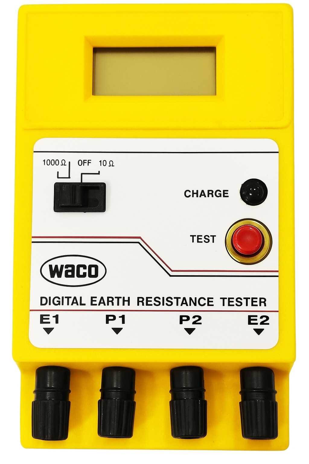
Digital Earth Tester
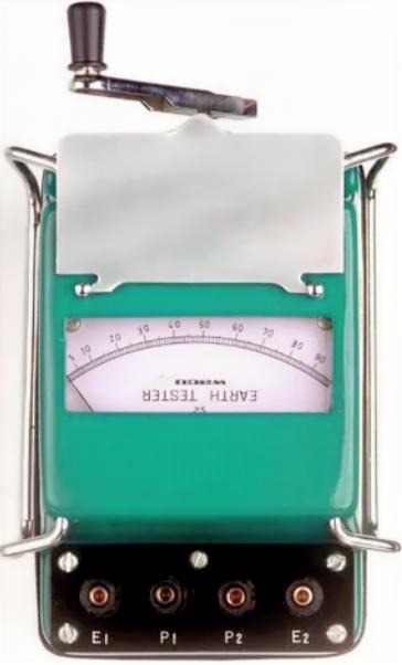
Analog Earth Tester
Construction of Earth Tester
Below is a detailed explanation of all the internal parts of an earth tester and what each one does.
1. DC Generator
Inside the tester, there is a small hand-driven or motor-driven DC generator. Its job is to supply the electrical power needed for testing.
2. Current Reverser
The DC produced by the generator is not used directly.
A current reverser converts the DC into a low-frequency alternating type of current.
This feature helps remove errors caused by soil polarisation and gives a more accurate reading.
3. Rectifier
The tester also has a rectifier unit.
It prepares the signal for the measurement circuit so that the potential coil attains a clean and stable voltage for proper indication.
4. Measuring System
The internal meter uses two coils:
a) Current Coil
This coil carries the test current that flows through the soil.
The amount of current depends on the resistance of the earth.
b) Potential Coil
This coil measures the voltage drop between two points in the soil.
The interaction of the current coil and potential coil offers a direct reading of earth resistance (R = V/I).
5. Terminals of the Earth Tester
The earth tester has four terminals:
- E1 (C1): Current terminal at the electrode under test.
- P1: Potential terminal at the electrode (usually bonded to E1).
- P2: Potential spike terminal—used to sense a voltage drop in the soil.
- E2 (C2): Current Spike Terminal— used to inject test current into the soil.
During testing, P1 and C1 are shorted using a link, as shown in the diagram.
6. Electrodes in the Ground
The earth tester works with three metal spikes driven into the soil:
- E (Earth Electrode) – The electrode whose resistance we want to measure
- P (Potential Spike) – Used to sense voltage
- C (Current Spike) – Used to inject current into the soil
By sending current and measuring voltage, the tester calculates the earth resistance accurately.

Working of Earth Tester
An earth tester works by sending a known current into the soil and measuring the voltage drop across two points in the ground. A DC generator within the tester generates current, which a current reverser transforms into a low-frequency alternating current to prevent soil polarisation. This alternating current flows through the earth electrode and the current electrode. A separate potential electrode senses the voltage developed in the soil due to this current. The current coil carries the test current, and the potential coil receives the voltage. Their combined action gives a pointer deflection that is proportional to V/I, which is the earth resistance. Thus, the tester directly shows the earth resistance on the meter.
Simple Connection of Earth Tester:
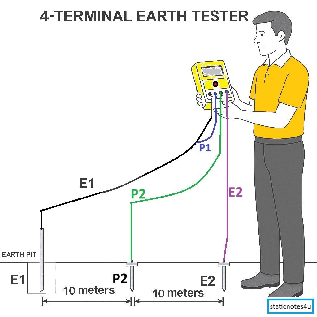
Connection Procedure of Earth Tester
- Place the Electrodes:
- Start with the main earth electrode (the one you’re testing).
- Insert two auxiliary spikes (metal rods) in a straight line outward from the electrode.
- Keep the potential spike (P2) about 5–10 metres away, and the current spike (E2) another 10–20 metres beyond that.
- Connect the Tester:
- Connect E1 of the tester to your main earth electrode.
- Connect P1 (often shorted to E1 using a small jumper) to the same electrode.
- Connect P2 lead to the potential spike in the ground.
- Connect E2 lead to the current spike in the ground.
- Switch On & Measure:
- Turn on the tester (set the range, e.g., 10 Ω or 1000 Ω).
- Press the TEST button or crank if it’s analogue.
- The tester sends a small AC current between E1 and E2, and measures the voltage between P1 and P2.
- It automatically calculates resistance using Ohm’s Law (R = V/I).
- Read the Display:
- The screen shows the earth resistance value in ohms (Ω).
- A good earthing system usually reads between 1 Ω to 5 Ω, depending on soil and standards.
Typical earth resistance values for different places
| Place / Installation | Recommended Earth Resistance |
|---|---|
| Power station / Substation | Less than 1 Ω |
| Transmission tower | Up to 5 Ω |
| Distribution transformer | Less than 2 Ω |
| Domestic (residential) installation | Up to 5 Ω |
| Industrial installation | Between 1 Ω to 2 Ω |
| Lightning arrester | Less than 1 Ω |
| General purpose earthing (ordinary ground) | Up to 10 Ω |
Applications of Earth Tester:
- Electricians use it to measure earth resistance.
- Engineers check the condition of earthing with it.
- People test soil resistance before installing earthing.
- Technicians compare earth resistance at different places.
- Users confirm proper earthing for electrical safety.
FAQs on Earth Tester
1. Why is the DC current not used directly for testing?
Direct DC causes soil polarisation, which creates errors in the readings. So pure DC is not suitable for accurate earth resistance measurement.
2. Why is an Earth Tester used?
It is used to ensure that fault current can safely flow to the ground. This helps protect people and electrical equipment from electric shock.
3. What are the parts of an Earth Tester?
Main parts of an Earth Tester include:
- Hand-driven generator or battery supply
- Current coil and potential coil
- Commutator or current reverser
- Terminals for electrodes and earth connection
4. What types of Earth Testers are available?
Common types are:
- Analog Earth Tester (hand-driven)
- Digital Earth Tester (battery or electronic type)
5. What is the normal value of earth resistance?
The ideal earth resistance should be less than 1 ohm for large substations and less than 5 ohms for normal electrical installations.
6. What causes high earth resistance?
High earth resistance can be caused by:
- Dry soil
- Loose connections
- Rusty or corroded electrodes
- Poor earthing wire contact
7. How can earth resistance be reduced?
You can reduce earth resistance by:
- Pouring salt and water around the electrode
- Using multiple earth rods
- Ensuring tight connections and clean contacts
8. Where is an Earth Tester used?
It is used in:
- Power stations and substations
- Electrical installations
- Building earthing systems
- Industrial plants
9. Why is regular earth testing important?
Regular testing ensures that the earthing system stays safe and effective.
It helps prevent electric shocks, equipment failure, and fire hazards.